
What is PWHT
One of the most common applications of our heat treatment is for post weld heat treatment. Superheat FGH can provide post weld heat treatment to your specifications or consult you on the best post weld heat treatment process for your metallurgy and application.
Post Weld Heat Treatment (in accordance with AWS D10.10M)
Post Weld Heat Treatment is performed after welding, generally at a higher temperature and with different objectives than Preheat/Inter-pass heating. PWHT may need to be applied without allowing the temperature to drop below the specified minimum for Preheat/Inter-pass heating. So in short you may have to apply the PWHT method with the work piece at temperatures up to 600° F (316° C).
Local PWHT of carbon and low alloy steels is typically performed below the lower critical transformation temperature and is therefore referred to as subcritical. The lower and upper critical transformation temperatures indicate where the crystal structure of steel begins and finally completes a change from body centered cubic to face centered cubic upon heating (the reverse upon cooling). And what this is saying, the molecules of the alloy will rearrange them self to a different configuration if we allow the temperature to reach the upper critical transformation. That will cause the properties of the metal to change, such as hardness and ductility.
There are several reasons why local supercritical PWHT (above the upper critical transformation temperature) such as annealing or normalizing is not desirable. First and foremost, the temperature gradients inherent to local PWHT would produce subcritical, inter-critical and supercritical temperature regions. Depending upon the prior heat treatment of the material, this could result in a detrimental effect upon properties (tensile/yield strength and impact toughness) and/or local inhomogeneity (irregularity).
Additionally, reduced material strength at supercritical temperatures creates a greater likelihood for distortion. For reasons relating to carbide precipitation and the need for rapid cooling, localized solution annealing of austenitic alloys such as 300 series stainless steels is also generally not desirable. The discussion of PWHT below and in other parts of the document refers to subcritical PWHT, unless otherwise noted.
Post Weld Heat Treatment can have both beneficial and detrimental effects. Three primary benefits of PWHT are recognized. These are tempering, relaxation of residual stresses and hydrogen removal. Consequential benefits such as avoidance of hydrogen induced cracking, dimensional stability, and improved ductility toughness and corrosion resistance result from the primary benefits. It is important that PWHT conditions be determined based upon the desired objectives. With regard to local PWHT this is especially true for stress relaxation.
Excessive or inappropriate PWHT temperatures and/or long holding times can adversely affect properties. The adverse effects can include decreased tensile strength, reduced creep strength, and notch toughness (generally caused by embrittlement due to precipitate formation). The influence of PWHT on properties primarily depends upon the composition of the weld metal and base metal and prior thermal and mechanical processing of the base metal. If PWHT is run at higher than specified temperatures and / or longer specified soak times the work piece can become more brittle than desired. The need for Post Weld Heat Treatment is usually driven by either a direct requirement within a particular fabrication or repair code or by service environment concerns. Requirements to apply PWHT are generally triggered by material type and thickness. These fabrication codes provide detailed requirements regarding local PWHT. PWHT is generally aimed at reducing susceptibility to brittle fracture, and as such is targeted to improve notch toughness and relax residual stress (pre-existing work piece stress, such as heat from welding, fabrication stresses, machining, cutting etc.).
The need for PWHT based upon service environment is not treated by the fabrication codes. Instead guidance may be found in recommended practices regarding service environment. Applying PWHT for service can have a variety of objectives. Reduction of hardness and stress relaxation are two of the more common objectives related to service environments. It is important to note that the threshold residual stress levels in such cases are often less than those required for brittle fracture related concerns, and more detailed requirements may therefore apply. The application of a PWHT, whether directed by code or desired by a customer, is a critical evolution. It ensures the work piece is correctly reconditioned giving the customer the most desirable levels of Hardness, Strength, and Ductility, this being the ultimate goal with every job we perform. So care and attention must always be given through every phase of a cycle to be controlled at the ideal temperature over the correctly allotted time frame
Understanding the areas of the work piece.
When dealing with the work piece there are some important areas that you need to be aware of and key terms, and they are: Weld area (w), Heat affected zone (HAZ), Soak Band (SB), Heated Band (HB), Gradient Control Band (GCB), Nominal thickness (t), and for Piping the Diameter (D), and Radius (R).
Weld Area and Heat Affected Zone
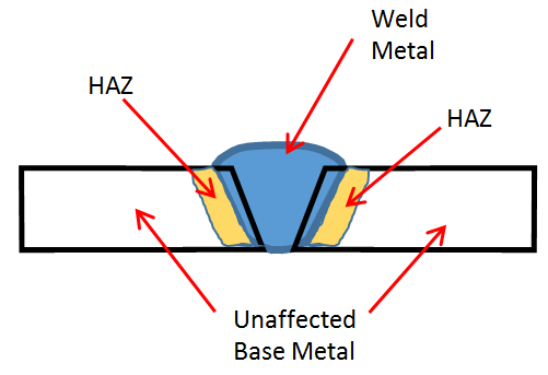
The terms Weld Area and Heat Affected Zone (HAZ) are defined as follows: in accordance with D10.10M the Weld Area is the Widest width of butt or attachment weld. Noted as W. Note this applies to a pipe, or plate; it can be applied to a local area or a 360 area of a pipe. Now the HAZ as seen in Figure 19 is described as, the area of the base material on the metal which has had its microstructure and properties altered by welding; Heat intensive cutting; and some time bending/ working an area. This is what we as a heat treating company are trying to fix, by restoring the HAZ to its normal condition.
Soak Band (in accordance with AWS D10.10M)
The Soak Band consists of the through thickness volume of metal, which is heated to the minimum but does not exceed the maximum required temperature. As a minimum, it should consist of the weld metal, HAZ, and any portion of the base metal adjacent to the weld being heated. The Soak Band Width is established to ensure that the required volume of metal achieves the desired effect.
Heated Band (in accordance with AWSD10.10M)
The next area we will be looking at is the Heated Band (HB). The HB encompasses the SB and has two major considerations. One it is large enough to insure that the minimum required temperature extends through the thickness in the SB. Two Local heating of a cylindrical shell will produce bending moments and shear stresses. These bending moments and shear stresses can cause distortion and/or induce residual stress in the weld region. The magnitude and location of these stresses are affected by the width of the HB and axial temperature distribution.
Gradient Control Band (in accordance with AWS D10.10M)
As the name implies, the primary function of this Band is to control the axial temperature gradient. It also serves to minimize heat losses in the heated Band (heat source). The characteristics of the insulation (both thickness and thermal properties) directly affect the power requirements of the heat source. The width of the insulated area directly affects the axial temperature gradient. The cited fabrication codes do not provide any guidance with regard to width.
Understanding the different codes we use ASME B31.1-Power Piping
This code prescribes minimum requirements for the design, materials, fabrication, erection, test, inspection, operation, and maintenance of piping systems typically found in electric power generating stations, industrial institutional plants, geothermal heating systems, and central and district heating and cooling systems. The code also covers boiler external piping for power boilers and high temperature, high pressure water boilers in which steam or vapor is generated at a pressure of more than 15 psig; and high temperature water is generated at pressures exceeding 160 psig and/or temperatures exceeding 250°F.This code will generally be used in power plants from natural gas such as AEP, to hydro electric plants.
ASME B31.3-Process Piping B
This code prescribes requirements for materials and components, design, fabrication, assembly, erection, examination, inspection, and testing of piping systems typically found in petroleum refineries; chemical, pharmaceutical, textile, paper, semiconductor, and cryogenic plants; and related processing plants and terminals. This Code applies to piping for all fluids including: (1) raw, intermediate, and finished chemicals; (2) petroleum products; (3) gas, steam, air and water; (4) fluidized solids; (5) refrigerants; and (6) cryogenic fluids.
Also included is piping which interconnects pieces or stages within a packaged equipment assembly.This code will generally be used in refineries, chemical and pharmaceutical plants.
ASME SECTION I
This section provides requirements for all methods of construction of power, electric, and miniature boilers; high temperature water boilers used in stationary service; and power boilers used in locomotive, portable, and traction service.
ASME SECTION III NB
This Subsection contains requirements for the material, design, fabrication, examination, testing, and overpressure protection of items which are intended to conform to the requirements for Class 1 construction (Those components that are part of the primary core cooling system). The rules of Subsection NB cover the requirements for assuring the structural integrity of items. This code will generally be used in nuclear power plants.
ASME SECTION III NC
This Subsection contains requirements for the material, design, fabrication, examination, testing, and overpressure protection of items which are intended to conform to the requirements for Class 2 construction. (Those components that are part of various important-to-safety emergency core cooling systems) The rules of Subsection NC cover the requirements for assuring the structural integrity of items. This code will generally be used in nuclear power plants.
ASME SECTION VIII Division 1
This Division of Section VIII provides requirements applicable to the design, fabrication, inspection, testing, and certification of pressure vessels operating at either internal or external pressures exceeding 15 psig. Such pressure vessels may be fired or unfired. Specific requirements apply to several classes of material used in pressure vessel construction, and also to fabrication methods such as welding, forging and brazing. It contains mandatory and nonmandatory appendices detailing supplementary design criteria, nondestructive examination and inspection acceptance standards.This code will generally be used in refineries, chemical and pharmaceutical plants.
ASME SECTION VIII Division 2
These rules provide an alternative to the minimum requirements for pressure vessels under Division 1 rules. In comparison to Division 1, Division 2 requirements on materials, design, and nondestructive examination are more rigorous; however, higher design stress intensity values are permitted. Division 2 rules cover only vessels to be installed in a fixed location for a specific service where operation and maintenance control is retained during the useful life of the vessel by the user who prepares or causes to be prepared the design specifications. These rules may also apply to human occupancy pressure vessels typically in the diving industry. (Hypobaric Chambers) This code will generally be used in nuclear power plants.
ASME SECTION VIII Division 3
This Division of Section VIII provides requirements applicable to the design, fabrication, inspection, testing, and certification of pressure vessels operating at either internal or external pressures generally above 10,000 psi. Such vessels may be fired or unfired. This pressure may be obtained from an external source, a process reaction, by the application of heat from a direct or indirect source, or any combination thereof. Division 3 rules cover vessels intended for a specific service and installed in a fixed location or relocated from work site to work site between pressurizations. The operation and maintenance control is retained during the useful life of the vessel by the user who prepares or causes to be prepared the design specifications. Division 3 does not establish maximum pressure limits for Section VIII, Divisions 1 or 2, or minimum pressure limits for this Division.This code will generally be used in nuclear power plants.